Waveguide Passive Components
Terminations & Attenuators
Drawcom provides a complete range of waveguide terminations, from precision low power test bench items to high power forced air cooled devices.
Specifications
Medium Power Terminations
| Part No. | Waveguide Size | Length (in.) | Maximum VSWR Any 10% of Bandwidth | Power Rating (W) |
| M0929-01 | 284 | 9.25 | 1.10 | 275 |
| M0929-02 | 229 | 8.75 | 1.10 | 225 |
| M0929-03 | 187 | 8.25 | 1.10 | 175 |
| M0929-04 | 159 | 7.00 | 1.10 | 125 |
| M0929-05 | 137 | 6.00 | 1.10 | 75 |
| M0929-06 | 112 | 5.00 | 1.10 | 75 |
| M0929-07 | 90 | 5.00 | 1.10 | 75 |
| M0929-08 | 75 | 3.25 | 1.10 | 75 |
| M0929-09 | 62 | 4.00 | 1.10 | 75 |
| M0929-10 | 51 | 3.75 | 1.10 | 40 |
| M0929-11 | 42 | 3.50 | 1.10 | 40 |
These are single element terminations with a power dissipation ranging from 3000 Watts for WR284 to 220 Watts for WR42, using convection cooling. Use of forced air cooling will increase the power dissipation capacity by about 50%. Maximum VSWR 1.10 optimized over any 10% of bandwidth.
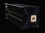
High Power Terminations
| Part No. * | Waveguide Size | Power Rating (W) | Dimension A (in.) | Dimension B (in.) | |
| Convection Cooling | Forced Air Cooling | ||||
| M1233-01 | 284 | 3000 | 4500 | 20.50 | 8.00 |
| M1233-03 | 187 | 1800 | 2600 | 15.00 | 5.75 |
| M1233-04 | 159 | 1500 | 2200 | 13.00 | 5.00 |
| M1233-05 | 137 | 1200 | 1800 | 12.00 | 4.50 |
| M1233-06 | 112 | 900 | 1300 | 10.00 | 4.00 |
| M1233-07 | 90 | 700 | 1000 | 7.50 | 3.50 |
| M1233-08 | 75 | 400 | 600 | 6.50 | 3.00 |
| M1233-09 | 62 | 300 | 400 | 5.00 | 2.50 |
| M1233-10 | 51 | 200 | 300 | 4.25 | 2.00 |
| M1233-11 | 42 | 150 | 220 | 4.00 | 1.75 |
| ORDERING INFORMATION
1. Specify model number. 2. Specify center frequency. 3. Specify flange code. *M1233 – Flat flange style only. |
ORDERING EXAMPLE | ||
|
PART NO. |
FREQUENCY |
FLANGE |
|
|
M0929-05 |
6.14 |
02 |
|
Low Power, Low VSWR Terminations (Sliding and Fixed)
Drawcom Sliding and Fixed Terminations are used for accurate return loss measurements. These units are intended for low power applications only.
The termination element is a specially tapered dissipating dielectric. The sliding model has a travel greater than one-half wavelength at the lowest operating frequency.
The VSWR values shown on the tables below for Model numbers M0931 and M0912 correspond to full waveguide bandwidth.
|
M0931 – Sliding Termination |
M0912 – Fixed Termination |
||||||||
|
Part No. |
WR Type |
Length (in.) |
Maximum VSWR |
Power Rating (W) |
Part No. |
WR Type |
Length (in.) |
Maximum VSWR |
Power Rating (W) |
| M0931 – 1 | 284 | 17.5 | 1.020 | 5.0 | M0912 – 1 | 284 | 10.5 | 1.020 | 6.0 |
| M0931 – 2 | 229 | 13.5 | 1.020 | 3.0 | M0912 – 2 | 229 | 7.5 | 1.020 | 4.0 |
| M0931 – 3 | 187 | 12.5 | 1.020 | 3.0 | M0912 – 3 | 187 | 6.5 | 1.020 | 4.0 |
| M0931 – 4 | 159 | 10.6 | 1.020 | 3.0 | M0912 – 4 | 159 | 6.0 | 1.020 | 4.0 |
| M0931 – 5 | 137 | 9.6 | 1.020 | 2.0 | M0912 – 5 | 137 | 5.5 | 1.020 | 3.0 |
| M0931 – 6 | 112 | 8.6 | 1.020 | 2.0 | M0912 – 6 | 112 | 5.5 | 1.020 | 3.0 |
| M0931 – 7 | 90 | 8.6 | 1.025 | 2.0 | M0912 – 7 | 90 | 5.5 | 1.025 | 3.0 |
| M0931 – 8 | 75 | 7.6 | 1.025 | 2.0 | M0912 – 8 | 75 | 4.5 | 1.025 | 2.0 |
| M0931 – 9 | 62 | 6.6. | 1.030 | 1.0 | M0912 – 9 | 62 | 4.0 | 1.025 | 1.0 |
| M0931 – 10 | 51 | 5.6 | 1.040 | 0.5 | M0912 – 10 | 51 | 3.5 | 1.030 | 0.5 |
| M0931 – 11 | 42 | 4.6 | 1.040 | 0.5 | M0912 – 11 | 42 | 3.5 | 1.030 | 0.5 |
| M0931 – 13 | 28 | 6.0 | 1.040 | 0.5 | M0912 – 13 | 28 | 2.5 | 1.035 | 0.5 |
ORDERING INFORMATION
1. Specify base model number.
2. Specify flange type required.
Low Power Fixed Attenuators
Low Power Fixed Attenuators use a resistance card through the broadwall of the precision waveguide. The attenuation value in dB, at the calibration frequency specified below, is indicated by a suffix to the model number. The attenuation flatness, over the full waveguide frequency range, is within 10% of the value of the total attenuation. The VSWR is less than 1.4 for the maximum attenuation show in the table below.
|
M2554 Low Power Fixed Attenuator |
||||||
|
Part No. |
WE Type |
Maximum Attenuation (dB) |
Max VSWR* |
Cal. Freq. (GHz) |
Power Rating (W) |
DIM A (in.) |
| M2554-1 | 284 | 50 | 1.15 | 3.3 | 1.5 | 16.00 |
| M2554- 2 | 229 | 50 | 1.15 | 4.1 | 1.5 | 15.00 |
| M2554- 3 | 187 | 50 | 1.15 | 4.9 | 1.5 | 13.00 |
| M2554- 4 | 159 | 50 | 1.15 | 6.0 | 1.5 | 12.00 |
| M2554- 5 | 137 | 50 | 1.15 | 7.0 | 1.0 | 10.00 |
| M2554- 6 | 112 | 50 | 1.15 | 8.5 | 1.0 | 8.00 |
| M2554- 7 | 90 | 50 | 1.15 | 10.3 | 1.0 | 6.00 |
| M2554- 8 | 75 | 50 | 1.15 | 12.5 | 1.0 | 5.00 |
| M2554- 9 | 62 | 50 | 1.15 | 15.2 | 1.0 | 4.50 |
| M2554- 10 | 51 | 50 | 1.15 | 18.5 | 1.0 | 4.00 |
| M2554- 11 | 42 | 50 | 1.15 | 22.5 | 0.5 | 3.50 |
| M2554- 12 | 34 | 35 | 1.20 | 27.5 | 0.5 | 3.00 |
| M2554- 13 | 28 | 35 | 1.20 | 33.2 | 0.5 | 3.00 |
| M2554- 14 | 22 | 35 | 1.20 | 41.5 | 0.5 | 3.00 |
ORDERING INFORMATION
Specify base model number and waveguide size from table above.
Specify attenuation required; e.g. -3 = 3 dB, -20 = 20 dB, -40 = 40 dB.
Specify flanges required
For special request add -S and specify; e.g. calibration frequency, calibration chart…
| ORDERING EXAMPLE | |||
| Part No. | W/G Size | Attenuation | Flange |
| M2554 | 8 | 30 | 1 - 1 |
| Part Number – M2554-8-30-1-1 | |||
The example describes a WR75 Fixed Attenuator with 30 dB attenuation and CPR G flanges on both ends.
Medium and High Power Fixed Attenuator
These attenuators are designed using broadwall directional couplers terminated at one end with a medium or high power termination.
Attenuation range is between 6 - 50 dB. The power handling is dependent on the termination used. The frequency range is the full waveguide band and typical flatness is ± 1 dB across the band. The return loss at input is 26 dB minimum. Overall dimensions may vary according to power rating and attenuation required.
|
M1306 Medium Power Attenuator |
M1307 High Power Attenuator |
||||
|
Part No. |
WR Type |
Power Rating (W) |
Part No. |
WR Type |
Power Rating (W) |
| M1306- 1 | 284 | 1000 | M1307 – 1 | 284 | 3000 |
| M1306- 4 | 159 | 400 | M1307 – 4 | 159 | 1500 |
| M1306- 5 | 137 | 350 | M1307 – 5 | 137 | 1200 |
| M1306- 6 | 112 | 250 | M1307 – 6 | 112 | 750 |
| M1306- 7 | 90 | 200 | M1307 – 7 | 90 | 600 |
| M1306- 8 | 75 | 100 | M1307 – 8 | 75 | 400 |
ORDERING INFORMATION
Specify base model number on the basis of power dissipation and waveguide size.
Specify attenuation required; e.g. -13 = 13 dB.
Specify flanges required.
| ORDERING EXAMPLE | |||
| Part No. | W/G Size | Attenuation | Flange |
| M1307 | 8 | 20 | 1 - 1 |
| Part Number – M1370-8-20-1-1 | |||
The example describes a WR75 High Power Fixed Attenuator with 20 dB attenuation and CPR G flanges on both ends
Low Power Variable Attenuators
The variable attenuator uses an adjustable resistance card through the precision broadwall of the waveguide. To achieve variable attenuation, the moving card is actuated by a precision micrometer. Calibration charts (5 points) for micrometer setting vs dB is provided with each attenuator. The calibration frequency is specified below. The attenuation flatness, over the full waveguide band and at maximum attenuation setting, is within 5 dB and the VSWR is better than 1.4.
|
M2370 Low Power Variable Attenuators |
||||||
|
Part No. |
WR Type |
Maximum Attenu. Range (dB) |
Max. VSWR* |
Cal. Freq. (GHz) |
Power Rating (W) |
DIM A (in.) |
| M2370 – 1 | 284 | 0.2 – 50 | 1.15 | 3.3 | 1.5 | 16.00 |
| M2370 – 2 | 229 | 0.2 – 50 | 1.15 | 4.1 | 1.5 | 15.00 |
| M2370 – 3 | 187 | 0.2 – 50 | 1.15 | 4.9 | 1.5 | 13.00 |
| M2370 – 4 | 159 | 0.2 – 50 | 1.15 | 6.0 | 1.5 | 12.00 |
| M2370 – 5 | 137 | 0.2 – 50 | 1.15 | 7.0 | 1.5 | 10.00 |
| M2370 – 6 | 112 | 0.2 – 50 | 1.15 | 8.5 | 1.0 | 8.00 |
| M2370 – 7 | 90 | 0.2 – 50 | 1.15 | 10.3 | 1.0 | 6.00 |
| M2370 – 8 | 75 | 0.2 – 50 | 1.15 | 12.5 | 1.0 | 5.00 |
| M2370 – 9 | 62 | 0.2 – 50 | 1.15 | 15.2 | 1.0 | 4.50 |
| M2370 – 10 | 51 | 0.2 – 50 | 1.15 | 18.5 | 1.0 | 4.00 |
| M2370 – 11 | 42 | 0.2 – 35 | 1.15 | 22.5 | 0.5 | 3.50 |
| M2370 – 12 | 34 | 0.2 – 35 | 1.20 | 27.5 | 0.5 | 3.00 |
| M2370 – 13 | 28 | 0.2 – 35 | 1.20 | 33.2 | 0.5 | 3.00 |
| M2370 – 14 | 22 | 0.2 – 35 | 1.20 | 41.5 | 0.5 | 3.00 |
ORDERING INFORMATION
1. Specify base model number and waveguide size from table above.
2. Specify flanges required
3. For special request add –S and specify; e.g. calibration frequency, calibration range, etc…
| ORDERING EXAMPLE | ||
| Part No. | W/G | Flanges |
| M2370 | 2 | 5 - 5 |
| Part Number – M2370-2-5-5 | ||
The example describes a WR229 Low Power Variable Attenuator with CMR flanges, 8 Tapped Holes on both sides.