Waveguide Passive Components
Rigid Waveguide Assembly
A comprehensive range of custom and catalogue rigid waveguide sections can be specified using the following data and model numbering.
Of course assemblies made to customer drawings and special requirements are always welcome.
Specifications
M1240 – Waveguide Straight Sections |
||
| Part No. | Waveguide Size | Minimum LENGTH (in.) |
| M1240-01 | 284 | 3 |
| M1240-02 | 229 | 3 |
| M1240-03 | 187 | 3 |
| M1240-04 | 159 | 3 |
| M1240-05 | 137 | 3 |
| M1240-06 | 112 | 2 |
| M1240-07 | 90 | 2 |
| M1240-08 | 75 | 2 |
| M1240-09 | 62 | 1 |
| M1240-10 | 51 | 1 |
| M1240-11 | 42 | 1 |
| M1240-13 | 28 | 1 |
| ORDERING EXAMPLE | ||
| PART NO. | LENGTH (INCHES) | FLANGE |
| M1240-06 | 144 | 01-02 |
| PART NUMBER – M1240-06-144-01-02 Specifies a straight rectangular WR112 waveguide section having a length of 144 inches with a CPR-G and a CPR-F cover flanges. Unless otherwise specified, material will be copper & painted black. | ||
Rectangular waveguide twist sections can be defined by the size of the waveguide, types of flanges, desired length (subject to the minimum specified in the table), desired amount of twist (0° to 90°) and direction of twist (right or left) from flange A to B. |
M1246 – Waveguide Twist Sections |
||
| Part No. | Waveguide Size | Minimum LENGTH (in.) |
| M1246-01 | 284 | 9.25 |
| M1246-02 | 229 | 8.00 |
| M1246-03 | 187 | 7.00 |
| M1246-04 | 159 | 6.00 |
| M1246-05 | 137 | 4.50 |
| M1246-06 | 112 | 3.75 |
| M1246-07 | 90 | 2.75 |
| M1246-08 | 75 | 2.25 |
| M1246-09 | 62 | 2.00 |
| M1246-10 | 51 | 1.50 |
| M1246-11 | 42 | 1.25 |
| M1246-13 | 28 | 1.00 |
| ORDERING EXAMPLE | |||
| PART NO. | DIRECTION & ANGLE | LENGTH (INCHES) | FLANGE |
| M1246-06 | R90 | 8 | 06-07 |
| PART NUMBER – M1246-06-R90-8-06-07 Specifies a rectangular waveguide WR112, right 90° twist, 8 inches long, with flange UG cover and UG choke.Unless otherwise specified, material will be copper & painted black. | |||
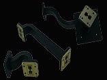
Waveguide Bend Assemblies |
|||||||
| M1699 - 90° CAST BENDS (INDOOR USE) | M1245 - 90° SWEPT BEND (OUTDOOR USE) | ||||||
| Part No. | W/G Size | Min. Length | Part No. | W/G Size | Min. Length | ||
| E Bend | H Bend | E Bend | H Bend | ||||
| M1699-01 | 284 | 3.75 | 3.25 | M1245-01 | 284 | 6.00 | 9.00 |
| M1699-02 | 229 | 3.25 | 2.75 | M1245-02 | 229 | 4.00 | 8.00 |
| M1699-03 | 187 | 2.75 | 2.25 | M1245-03 | 187 | 4.00 | 7.00 |
| M1699-04 | 159 | 2.75 | 2.25 | M1245-04 | 159 | 4.00 | 5.00 |
| M1699-05 | 137 | 2.25 | 2.00 | M1245-05 | 137 | 3.00 | 4.00 |
| M1699-06 | 112 | 2.00 | 1.75 | M1245-06 | 112 | 3.00 | 3.00 |
| M1699-07 | 90 | 1.75 | 1.25 | M1245-07 | 90 | 1.25 | 1.75 |
| M1699-08 | 75 | 1.50 | 1.37 | M1245-08 | 75 | 0.75 | 1.00 |
| M1699-09 | 62 | 1.37 | 1.25 | M1245-09 | 62 | 0.75 | 1.00 |
| M1699-10 | 51 | 1.25 | 1.12 | M1245-10 | 51 | 0.75 | 1.00 |
| M1699-11 | 42 | 1.00 | 1.00 | M1245-11 | 42 | 0.75 | 1.00 |
| M1699-13 | 28 | 1.00 | 1.00 | M1245-13 | 28 | 0.50 | 0.75 |
| Note: All dimensions are in inches. Unless otherwise specified, material will be copper & painted black. | |||||||
| ORDERING INFORMATION
1. Specify model Number. 2. Specify ’E’ or ’H’ Bend (90°). 3. Specify A and B lengths in inches. 4. Specify flange code. 5. Specify frequency range. |
ORDERING EXAMPLE | ||||
| PART NO. | BEND TYPE | A DIM | B DIM | FLANGE | |
| M1699 -05 | E90 | 10 | 12.5 | 04-05 | |
| PART NUMBER – M1699-5-E90-10-12.5-04-05 | |||||