Waveguide Passive Components
Flexible Waveguide
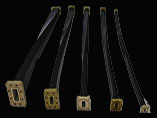
Flexible waveguide assemblies are available from WR28 to WR284 with North American or European Flange configurations.
Specifications
Electrical Specifications for Twistable M1640 & Non-Twistable M1650
| Dash No. | IEC-R ( ) | E/A Size WR | Matching Rigid W/G Internal Dimensions (in.) | Operation Freq Band (GHz) | Nominal Test Freq. For Attenuation (GHz) | Maximum IL Attenuation (dB/ft.) | Maximum VSWR CPR/CPR/ OR COV./Cover Flanges <36’ >36’ | Maximum VSWR Plain/ Choke Flanges CW <36” >36” | Power Rating M1640 CW (kW) | Power Rating M1650 CW (kW) |
| 01 | 32 | 284 | 2.840 X 1.340 | 2.60 - 3.95 | 3.15 | 0.03 | 1.03 1.07 | 1.07 1.10 | 6.5 | 8.5 |
| 02 | 40 | 229 | 2.290 X 1.145 | 3.30 - 4.90 | 3.85 | 0.03 | 1.03 1.07 | - - | - | - |
| 03 | 48 | 187 | 1.872 X 0.872 | 3.95 - 5.85 | 4.75 | 0.04 | 1.04 1.07 | 1.07 1.10 | 3.00 | 3.40 |
| 04 | 58 | 159 | 1.590 X 0.795 | 4.90 - 7.05 | 5.90 | 0.05 | 1.04 1.08 | 1.08 1.10 | 2.5 | 2.50 |
| 05 | 70 | 137 | 1.372 X 0.622 | 5.85 - 8.20 | 6.45 | 0.06 | 1.04 1.09 | 1.09 1.10 | 2.00 | 1.70 |
| 06 | 84 | 112 | 1.122 X 0.497 | 7.05 - 10.00 | 9.40 | 0.07 | 1.06 1.10 | 1.10 1.13 | 1.26 | 0.80 |
| 07 | 100 | 90 | 0.900 X 0.400 | 8.20 - 12.40 | 9.40 | 0.09 | 1.06 1.10 | 1.10 1.13 | 0.96 | 0.62 |
| 08 | 120 | 75 | 0.750 X 0.375 | 10.00 - 15.00 | 13.70 | 0.13 | 1.08 1.10 | 1.10 1.13 | 0.75 | 0.50 |
| 09 | 140 | 62 | 0.622 X 0.311 | 12.40 - 18.00 | 14.00 | 0.16 | 1.09 1.13 | 1.13 1.16 | 0.22 | 0.30 |
| 10 | 180 | 51 | 0.510 X 0.255 | 15.00 - 22.00 | 18.50 | 0.35 | 1.12 1.18 | 1.17 1.20 | 0.14 | 0.23 |
| 11 | 220 | 42 | 0.420 X 0.170 | 18.00 - 26.50 | 22.00 | 0.38 | 1.17 1.23 | 1.20 1.25 | 0.10 | 0.12 |
| 13 | 320 | 28 | 0.280 X 0.140 | 26.50 - 40.00 | 34.00 | 0.60 | 1.19 | 1.30-36” | 0.10 | N/A |
| ORDERING INFORMATION | ||||
| Part No. | W/G Size | Length (in. or mms) | Jacket | *Flanges & Flange Finish |
| M1640 | 07 | 12 | N | 06 - 07 - U |
| PART NUMBER – M1640-07-12-N-06-07-UThe above is a WR90 Flex Twist 12”- long neoprene jacket with cover and choke flanges – flanges unplated irridited & polished. Specify flanges – flange numeric codes*Brass unless otherwise requested |
| JACKET/PAINT | FLANGE FINISH CODES | |
| Code | Finish | |
| P = Black Paint (M1650 only) | C - | Both flanges cadmium-plated and passivated |
| S = Silicone | U - | Both flanges unplated irridited and polished |
| N= Neoprene | S - | Both flanges sliver-plated |
| T - | Both flanges tin-plated | |
Mechanical Specifications for Twistable M1640 & Non-Twistable M1650
| Dash NO | IEC-R ( ) | EIA Size WR | Twist & Non– Twist (M1640 & M1650) | Twist Only (M1640) | MaximumOperating Pressure | ||||||
| Bending Rating | Twisting Rating | ||||||||||
| Static | Repeated | Static | Repeated | Length | M1640 psig | M1650 psig | |||||
| E-plane Rad (in.) | H-plane Rad (in.) | E-plane Rad (in.) | H-plane Rad (in.) | Tolerance (±deg./ft.) | Twist (±deg./ft.) | Non- twist (±in./ft.) | |||||
| 01 | 32 | 284 | 7.0 | 14.0 | 28.0 | 56.0 | 32 | 8 | 1/8 | 20 | 40 |
| 02 | 40 | 229 | 6.5 | 13.0 | 26.0 | 52.0 | 40 | 10 | 1/8 | 30 | 40 |
| 03 | 48 | 187 | 6.5 | 13.0 | 26.0 | 52.0 | 48 | 12 | 1/8 | 30 | 40 |
| 04 | 58 | 159 | 5.0 | 10.0 | 20.0 | 40.0 | 56 | 14 | 1/8 | 30 | 40 |
| 05 | 70 | 137 | 4.0 | 8.0 | 16.0 | 32.0 | 64 | 16 | 1/8 | 30 | 40 |
| 06 | 84 | 112 | 3.0 | 6.0 | 12.0 | 24.0 | 80 | 20 | 1/8 | 35 | 50 |
| 07 | 100 | 90 | 2.5 | 5.0 | 10.0 | 20.0 | 96 | 24 | 1/8 | 45 | 50 |
| 08 | 120 | 75 | 2.5 | 4.5 | 10.0 | 20.0 | 112 | 28 | 1/8 | 45 | 50 |
| 09 | 140 | 62 | 2.0 | 4.0 | 8.0 | 16.0 | 136 | 34 | 1/8 | 45 | 50 |
| 10 | 180 | 51 | 2.0 | 4.0 | 8.0 | 16.0 | 136 | 34 | 1/8 | 45 | 60 |
| 11 | 220 | 42 | 1.5 | 3.0 | 6.0 | 12.0 | 155 | 45 | 1/8 | 45 | 60 |
| 13 | 320 | 28 | T.B.A | ||||||||
| CONSTRUCTION -
The basic construction of the guide is similar for both twistable and non-twistable versions and, irrespective of size or individual specification, consists of an inner core, two connecting flanges soft-soldered into position, and a protective outer jacket. |
| THE CORE -
The core is manufactured from pre-convoluted brass strip helically wound to extremely close tolerances around a rectangular mandrel. Twistable cores (M1640) are silver-clad and are locked by a plated copper sealing wire inserted into their seam during winding. At this stage pressurization is not possible. In order to hold pressure the flexible twistable waveguide must be encased in a rubber jacket. Non-twistable cores (M1650) are also silver-clad and are locked by solder wire which is then melted to form a continuous solder fillet running the entire length of the seam. (M1650) can be pressurized without a rubber jacket. |
| NEOPRENE -
• Shore hardness: 45° -50° • Shore hardness: -50° +100° |
| SILICONE -
• Shore hardness: 50° -55° • Operating temp.: -55°C to + 135°C |