Waveguide Passive Components
Circulators & Isolators
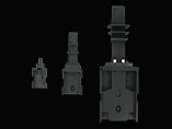
Drawcom’s Waveguide Circulators and Isolators are specifically designed to meet the requirements of high capacity and high performance microwave systems. The product line covers the frequency range from 2.7 GHz to 40 GHz.
Specifications
Waveguide Circulators
|
Part No. |
Frequency (GHz) |
Waveguide Type |
Minimum Isolation (dB) |
Maximum Insertion Loss (dB) |
Max VSWR |
Maximum Forward Power (W - cw) |
Style |
Flange Type |
| M0977-1 | 3.50 - 4.20 | WR229 | 26 | 0.20 | 1.10 | 400 | MWC1 | CMR |
| M0977-2 | 3.50 - 4.20 | WR229 | 26 | 0.20 | 1.10 | 400 | MWC1 | CPR |
| M1399 | 3.50 - 4.20 | WR229 | 26 | 0.20 | 1.10 | 400 | MWC1 | CPR |
| M2597 | 4.40 - 5.00 | WR187 | 30 | 0.10 | 1.065 | 350 | MWC2 | CMR |
| M0952-1 | 5.85 - 6.45 | WR137 | 26 | 0.20 | 1.10 | 300 | MWC1 | CPR |
| M0952-2 | 5.85 - 6.45 | WR137 | 26 | 0.20 | 1.10 | 300 | MWC1 | CMR |
| M1400-1 | 5.85 - 6.45 | WR137 | 30 | 0.10 | 1.065 | 2000 | MWC3 | Note 1 |
| M1400-2 | 5.8 - 7.125 | WR137 | 26 | 0.15 | 1.12 | 2000 | MWC3 | Note 1 |
| M1100-1 | 6.40 - 7.20 | WR137 | 26 | 0.25 | 1.10 | 300 | MWC1 | CPR |
| M1100-2 | 6.40 - 7.20 | WR137 | 26 | 0.25 | 1.10 | 300 | MWC1 | CMR |
| M0975 | 7.10 - 8.50 | WR112 | 26 | 0.15 | 1.10 | 300 | MWC3 | COVER |
| M1138 | 7.90 - 8.40 | WR112 | 30 | 0.15 | 1.065 | 1800 | MWC3 | Note 2 |
| M0957 | 9.30 - 9.80 | WR90 | 25 | 0.20 | 1.12 | 100 | MWC3 | COVER |
| M2434-2 | 10.70 - 11.70 | WR90 | 28 | 0.15 | 1.08 | 100 | MWC1 | Note 1 |
| M2381 | 10.70 - 11.70 | WR90 | 30 | 0.15 | 1.065 | 200 | MWC3 | Note 2 |
| M1466 | 10.70 - 11.70 | WR75 | 23 | 0.20 | 1.15 | 100 | MWC3 | COVER |
| M1898 | 11.00 - 12.70 | WR75 | 21 | 0.15 | 1.20 | 500 | MWC3 | COVER |
| M1067-1 | 11.70 - 12.20 | WR75 | 28 | 0.20 | 1.08 | 100 | MWC3 | COVER |
| M1067-2 | 12.50 - 12.75 | WR75 | 28 | 0.20 | 1.08 | 100 | MWC3 | COVER |
| M1506 | 12.00 - 12.70 | WR75 | 23 | 0.20 | 1.15 | 400 | MWC3 | COVER |
| M2062 | 14.00 - 14.50 | WR75 | 26 | 0.10 | 1.10 | 900 | MWC3 | COVER |
| M1167 | 14.40 - 15.35 | WR62 | 26 | 0.30 | 1.10 | 200 | MWC3 | COVER |
| M2594 | 18.60 - 19.90 | WR42 | 20 | 0.30 | 1.22 | 20 | MWC3 | COVER |
| M2595 | 17.50 - 19.50 | WR42 | 18 | 0.35 | 1.23 | 20 | MWC3 | COVER |
| M2596 | 19.00 - 20.60 | WR42 | 18 | 0.35 | 1.26 | 20 | MWC3 | COVER |
| M2298 | 27.00 - 30.50 | WR28 | 20 | 0.25 | 1.22 | 110 | MWC3 | Note 2 |
| M2021 | 33.00 - 37.00 | WR28 | 17 | 0.40 | 1.30 | 10 | MWC3 | Note 2 |
Note 1: Flange per customer require, (see Flange Numeric Codes) some restrictions may apply.
Note 2: Cover tapped.
Waveguide Isolators
|
Part No. |
Frequency (GHz) |
Waveguide Type |
Minimum Isolation (dB) |
Maximum Insertion Loss (dB) |
Max VSWR |
Maximum Forward Power (W - cw) |
Maximum Reverse Power (W - cw) |
Circulator Model (Cross Reference) |
| M1093 | 3.50 - 4.20 | WR229 | 26 | 0.15 | 1.10 | 400 | 10 | M0977 |
| M0980 | 5.90 - 6.45 | WR137 | 26 | 0.20 | 1.10 | 300 | 5 | M0952 |
| M1391-1 | 6.45 - 6.45 | WR137 | 30 | 0.10 | 1.065 | 2000 | 150 | M1400-1 |
| M2056 | 5.85 - 6.45 | WR137 | 26 | 0.20 | 1.12 | 300 | 10 | M0952 |
| M1391-2 | 5.80 - 7.125 | WR137 | 25 | 0.15 | 1.12 | 2000 | 150 | M1400-2 |
| M1077 | 6.40 - 7.20 | WR137 | 26 | 0.20 | 1.10 | 300 | 5 | M1100 |
| M1285 | 7.70 - 8.30 | WR112 | 26 | 0.15 | 1.10 | 300 | 10 | M0975 |
| M1174 | 7.90 - 8.40 | WR112 | 23 | 0.15 | 1.15 | 1800 | 75 | M1138 |
| M2115 | 9.20 - 10.20 | WR90 | 23 | 0.20 | 1.15 | 100 | 75 | M0957 |
| M1287 | 10.70 - 11.70 | WR90 | 28 | 0.15 | 1.08 | 100 | 2 | M2434-2 |
| M1467 | 10.70 - 11.70 | WR75 | 23 | 0.20 | 1.15 | 100 | 5 | M1466 |
| M2074 | 11.00 - 13.00 | WR75 | 23 | 0.20 | 1.15 | 100 | 10 | M1466 |
| M0992 | 11.70 - 12.20 | WR75 | 28 | 0.20 | 1.10 | 100 | 5 | M1067-1 |
| M1857 | 11.70 - 12.20 | WR75 | 26 | 0.15 | 1.10 | 100 | 75 | M1067-1 |
| M1743 | 14.00 - 14.50 | WR75 | 26 | 0.15 | 1.10 | 900 | 15 | M2062 |
| M2173 | 18.60 - 19.90 | WR42 | 20 | 0.30 | 1.22 | 20 | 2 | M2594 |
| M2359 | 17.50 - 19.50 | WR42 | 18 | 0.35 | 1.28 | 20 | 2 | M2595 |
| M2360 | 19.00 - 20.60 | WR42 | 18 | 0.35 | 1.28 | 20 | 2 | M2596 |
| M2149 | 27.00 - 30.00 | WR28 | 20 | 0.25 | 1.22 | 100 | 1 | M2298 |
| M2163 | 28.50 - 30.50 | WR28 | 20 | 0.25 | 1.22 | 100 | 1 | M2298 |
| M2373 | 34.00 - 36.00 | WR28 | 23 | 0.40 | 1.15 | 10 | 1 | M2021 |
ORDERING INFORMATION
Circulators
1. Select model from table.
2. Specify direction of circulation, for clockwise circulation (standard), add C. for counter-clockwise circulation, add A following base model number.
3. Select flange if applicable (see Flange Numeric Codes). Add suffix P if pressurization is required (3 pslg is standard).
| ORDERING EXAMPLE | ||||
| Part No. | Circulation | Flanges | Pressure | |
| M1400-1 | A | 1 | P | |
| Part Number – M1400-1-A1-P | ||||
The example describes a WR137 circulator (5.85 - 6.45 GHz with counter-clockwise circulation and CPR-G flanges with pressurization
ORDERING INFORMATION
Isolators
1. Select model from table.
2. Specify direction of circulation, for clockwise circulation (standard), add C. for counter-clockwise circulation, add A following base model number.
3. Specify termination port.
4. Select flange if applicable (see Flange Numeric Codes).
5. Add suffix P if pressurization is required (3 pslg is standard).
| ORDERING EXAMPLE | ||||
| Part No. | Circulation | Termination | Flange | Pressure |
| M2115 | C | 3 | 5 | - |
| Part Number – M2115-C-3-5 | ||||
The example describes a WR90 Isolator with clockwise circulation terminated on Port 3 with CMR tapped flanges
| ORDERING EXAMPLE | ||||
| Part No. | Circulation | Termination | Flange | Pressure |
| M1391-1 | A | 1 | 5 | - |
| Part Number – M1391-1-A-1-5 | ||||
The example describes a WR137 Isolator (5.85 - 6.425) with counter-clockwise circulation, terminated on Port 1 with CMR tapped flanges
If the above tables and ordering information do not fulfil your needs, please let us quote against your specification.