Waveguide Passive Components
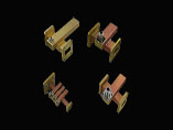
Cross – Guide Couplers
- Coupling value is 25 dB min. and 60 dB max.
- Coupling accuracy and flatness depend on frequency and bandwidth, typical values are ± 0.5 dB over 500 MHz.
- Minimum directivity is 20 dB.
- Return loss in main arm typically exceeds 26 dB.
- Return loss in secondary arm typically exceeds 19 dB (coupling-dependent).
Specifications
Single Arm Cross-Guide Couplers
| Part No. | Waveguide Size | Dimension (in.) | ||
| A | B | C | ||
| M*** - 01 | 284 | 7.50 | 3.75 | 5.00 |
| M*** - 02 | 229 | 7.00 | 3.50 | 4.75 |
| M*** - 03 | 187 | 6.50 | 3.25 | 4.50 |
| M*** - 04 | 159 | 6.00 | 3.00 | 4.00 |
| M*** - 05 | 137 | 5.25 | 3.00 | 4.00 |
| M*** - 06 | 112 | 4.20 | 2.10 | 3.00 |
| M*** - 07 | 90 | 4.00 | 2.00 | 2.75 |
| M*** - 08 | 75 | 3.75 | 1.87 | 2.50 |
| M*** - 09 | 62 | 3.50 | 1.75 | 2.37 |
| M*** - 10 | 51 | 3.10 | 1.50 | 2.25 |
| M*** - 11 | 42 | 2.20 | 1.10 | 1.50 |
Double and Triple Arm Cross-Guide Couplers
| Part No. | Waveguide Size | Dimension (in.) | ||
| A | B | C | ||
| M*** - 01 | 284 | 7.50 | 3.75 | 5.00 |
| M*** - 02 | 229 | 7.00 | 3.50 | 4.75 |
| M*** - 03 | 187 | 6.50 | 3.25 | 4.50 |
| M*** - 04 | 159 | 6.00 | 3.00 | 4.00 |
| M*** - 05 | 137 | 5.25 | 3.00 | 4.00 |
| M*** - 06 | 112 | 4.20 | 2.10 | 3.00 |
| M*** - 07 | 90 | 4.00 | 2.00 | 2.75 |
| M*** - 08 | 75 | 3.75 | 1.87 | 2.50 |
| M*** - 09 | 62 | 3.50 | 1.75 | 2.37 |
| M*** - 10 | 51 | 3.10 | 1.50 | 2.25 |
| M*** - 11 | 42 | 2.20 | 1.10 | 1.50 |
ORDERING INFORMATION
1. Specify model number by including*** appropriate model number.
2. Specify coupling value, e.g., -25 for 25 dB min.
3. Specify coupling direction, e.g., reverse or forward, by adding R or F to coupling value.
4. Specify flange code (see flange guide).
5. Specify if pressurization is required.
6. Specify frequency range.
| ORDERING EXAMPLE | ||||
| Part No. | COUPLING 1st Arm | COUPLING 2nd Arm | FLANGES P1-P2 | |
| M167-08 | 25F | 35F | 06 - 06 | |